


Normal

ON after a delay
The output turns ON after the set delay time.

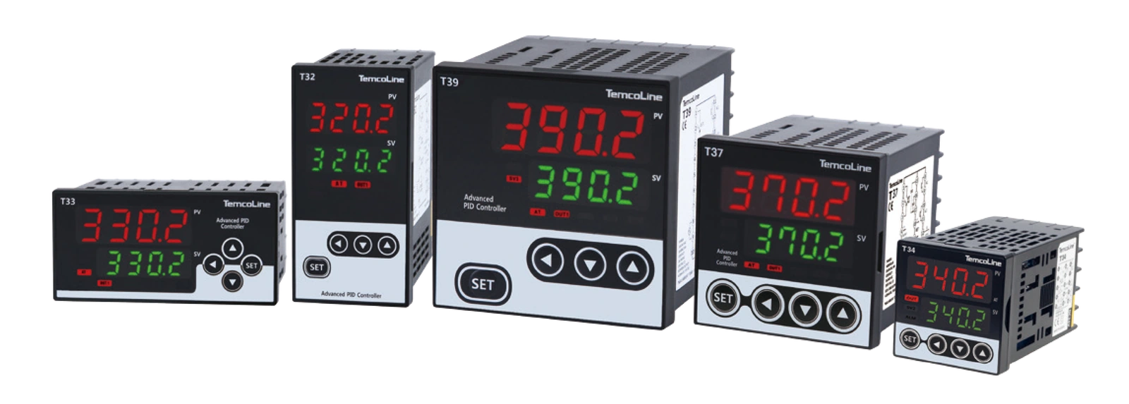



Standard PID Temperature Controllers
Cost-effective, high-accuracy controllers with 6 timer modes and practical features for fast, stable control.
Fast response
for stable control performance
Normal · T1~T5
A choice of timer modes
24 input types and 4 output types
for varied sensors and control needs
The Super 2-degree-of-freedom PID algorithm and Fast Auto-Tuning provide fast response and stable control.
Supports 24 input types, including TC, RTD, voltage and current, and 4 output types.
Adjusts the sampling period according to the SG-PID algorithm.
Supports Normal and T1~T5 modes and digital input (DI). See below for timer settings and operation.
Supports 20 alarm/event types and up to 3 contact outputs.
Signals a control-loop fault through an alarm contact.
Provides a dedicated run/stop contact output for the inverter interface.
Supports PV/SV/MV retransmission (4~20 mA) and sensor power (12 V DC, 25 mA). Check each model's configuration.
Choose the mode for the required start method and output operation.
The output turns ON after the set delay time.
Starts automatically and turns the output ON for the set time, once.
Starts manually and turns the output ON for the set time, once.
A manually started one-shot operation without a temperature condition.
Set the ON time for repeated operation from the front panel.
Set the OFF time for repeated operation from the front panel.
Refer to the original documents for setup procedures and detailed timing.
| General | |
|---|---|
| Supply voltage and order code | Final digit 0 · Standard power supply100~240 V AC, 50/60 Hz (permissible range: 85~265 V AC) Final digit 1 · Optional 24 V supply24 V AC/DC (permissible range: 20~28 V AC/DC) |
| Power consumption | 8 VA maximum |
| Operating environment | -10~50 °C / 25~85 % RH (no condensation or freezing) |
| Weight | T32, T33, T37: 310 g / T34: 200 g / T39: 420 g Includes brackets and accessories. Optional features add 30 g. |
| Input and measurement | |
| Thermocouple (TC) | K, J, T, E, R, B, S, L, N, U, C(W5), D(W3) |
| RTD | KPt100(KS), JPt100(JIS), Pt100(DIN) |
| Current and voltage inputs | 4~20 mA DC / 1~5 V DC / -10~20 mV DC / 0~100 mV DC |
| Measurement accuracy | ±0.3 % of FS + 1 digit |
| Input impedance | Current: 250 Ω / Voltage (including TC): at least 1 MΩ RTD lead resistance: 10 Ω or less, with equal resistance in all three leads |
| Input sampling period | 50~250 ms (variable according to the SG-PID algorithm) |
| Control and output | |
| Control methods | Super 2-degree-of-freedom PID (SG-PID), Fast Auto-Tuning |
| Relay output | 1 changeover contact, 250 V AC, 3 A (resistive load) Electrical life: at least 100,000 operations / Time-proportional PID or ON/OFF output |
| Voltage (SSR) output | 15 V DC, 25 mA / Built-in short-circuit protection / Voltage pulse (time-proportional PID) |
| Current (SCR) output | 4~20 mA DC / Permissible load impedance: 600 Ω or less / Continuous PID output |
| External input (DI) | ON: 1 kΩ or less / OFF: at least 100 kΩ External control inputs for SV1 and SV2 |
| Retransmission output | 4~20 mA DC / Load: 600 Ω or less / Resolution: approximately 1/4600 PV (measured value), SV (set value), MV (control output, %), SPS (sensor module power supply) |
| Alarm output | 1 normally open contact, 250 V AC, 3 A (resistive load) ALARM 1/2 shared with LBA; 20 independent event types and loop break alarm |
I/O, communication and alarm configurations depend on the model and selected options. Check the model configurations below and the product label.
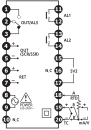 Enlarge vector drawing
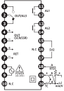 Enlarge vector drawing
 Enlarge vector drawing
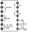 Enlarge vector drawing
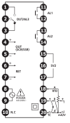 Enlarge vector drawing


