


C00 / C01
StandardAdd external DI input

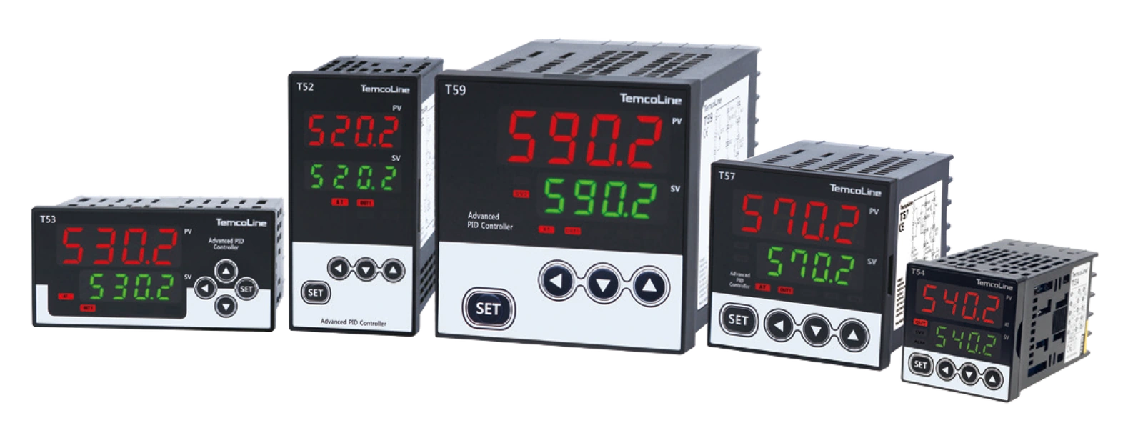



Advanced PID Temperature Controllers
PID temperature controllers with advanced features for stable, precise control in industrial applications.
A high-accuracy control algorithm
for stable control performance
Simultaneous heating and cooling
for varied control applications
Modbus ASCII / RTU,
PC-Link support
The Super 2-degree-of-freedom PID algorithm and Fast Auto-Tuning provide fast response and stable control.
Supports 24 input types, including TC, RTD, voltage and current, and 4 output types.
Adjusts the sampling period according to the SG-PID algorithm.
A dedicated PID algorithm for simultaneous heating/cooling control accommodates varied control applications.
A fully isolated communication port supports Modbus ASCII/RTU and PC/TL-Link. Check the options available for each model.
Sync-Master/Slave settings support synchronized communication with up to 250 units.
Monitor heater condition using CT current monitoring and accumulated heater operating time. Optional feature.
Supports run/stop, manual control and ramp control modes.
Corrects measured values by segment to reduce deviations caused by the operating environment.
Provides monitoring-only mode and stores the peak value when an alarm occurs.
Supports 20 alarm types, 3 event output points, output-port reassignment and AND/OR logic.
Remote monitoring and data viewer software is included as standard.
| General | |
|---|---|
| Supply voltage and order code | Final digit 0 · Standard power supply100~240 V AC, 50/60 Hz (permissible range: 85~265 V AC) Final digit 1 · Optional 24 V supply24 V AC/DC (permissible range: 20~28 V AC/DC) |
| Power consumption | 8 VA maximum |
| Operating environment | -10~50 °C / 25~85 % RH (no condensation or freezing) |
| Weight | T52, T53, T57: 310 g / T54: 200 g / T59: 420 g Includes brackets and accessories. Optional features add 30 g. |
| Input and measurement | |
| Thermocouple (TC) | K, J, T, E, R, B, S, L, N, U, C(W5), D(W3) |
| RTD | KPt100(KS), JPt100(JIS), Pt100(DIN) |
| Current and voltage inputs | 4~20 mA DC / 1~5 V DC / -10~20 mV DC / 0~100 mV DC |
| Measurement accuracy | ±0.3 % of FS + 1 digit |
| Input impedance | Current: 250 Ω / Voltage (including TC): at least 1 MΩ RTD lead resistance: 10 Ω or less, with equal resistance in all three leads |
| Input sampling period | 50~250 ms (variable according to the SG-PID algorithm) |
| Control and output | |
| Control methods | Super 2-degree-of-freedom PID (SG-PID), Fast Auto-Tuning |
| Relay output | 1 changeover contact, 250 V AC, 3 A (resistive load) Electrical life: at least 100,000 operations / Time-proportional PID or ON/OFF output |
| Voltage (SSR) output | 15 V DC, 25 mA / Built-in short-circuit protection / Voltage pulse (time-proportional PID) |
| Current (SCR) output | 4~20 mA DC / Permissible load impedance: 600 Ω or less / Continuous PID output |
| External input (DI) | ON: 1 kΩ or less / OFF: at least 100 kΩ External control inputs for SV1, SV2 and SV3 |
| Retransmission output | 4~20 mA DC / Load: 600 Ω or less / Resolution: approximately 1/4600 PV (measured value), SV (set value), MV (control output, %), SPS (sensor module power supply) |
| Alarm output | 1 normally open contact, 250 V AC, 3 A (resistive load) ALARM 1/2 shared with HBA (CT); measured heater current: 0.1~38.0 A AC (resolution: 0.1 A) |
| Communication · Optional feature | |
| Communication interface | Fully isolated 2-wire RS-485 Maximum 19,200 bps / Up to 99 units (32 units recommended) |
| Supported protocols | PC/TL-Link, Modbus ASCII·RTU, Sync-Master/Slave |
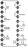
I/O, communication and alarm configurations depend on the model and selected options. Check the model configurations below and the product label.
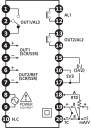 Enlarge vector drawing
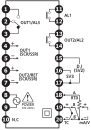 Enlarge vector drawing
 Enlarge vector drawing
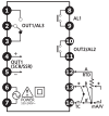 Enlarge vector drawing
 Enlarge vector drawing


